This quick tour will demonstrate the main features of USE.
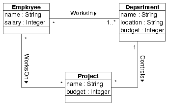
Consider the following UML class diagram for a simple model describing employees, departments, projects, and their relationships to each other.
We extend the model by the following four constraints which place further restrictions on systems conforming to the model. The constraints are first given in natural language and will later be expressed more formally in OCL (Object Constraint Language).
Constraints:
The goal of applying the USE tool is to interactively validate the above model and the constraints. Objects and links can be created which constitute a system state reflecting a snapshot of a running system. In every system state, the constraints are automatically checked for validity.
The USE tool expects as input a textual description of a model and its constraints. The above class diagram must therefore be first translated into a USE specification (a possible extension to USE would be the import of an XMI file created by a CASE tool like Argo UML or Rational Rose.). The first part of the specification shown below describes the structural information of the class diagram.
In the second part of the specification, we define the constraints in OCL. Each constraint is defined as an invariant in context of a class.
-- OCL constraints

constraints

context Department
    -- the number of employees working in a department must
    -- be greater or equal to the number of projects
    -- controlled by the department
  inv MoreEmployeesThanProjects:
    self.employee->size >= self.project->size

context Employee
    -- employees get a higher salary when they work on
    -- more projects
  inv MoreProjectsHigherSalary:
    Employee.allInstances->forAll(e1, e2 |
      e1.project->size > e2.project->size
        implies e1.salary > e2.salary)

context Project
    -- the budget of a project must not exceed the
    -- budget of the controlling department
  inv BudgetWithinDepartmentBudget:
    self.budget <= self.department.budget

    -- employees working on a project must also work in the
    -- controlling department
  inv EmployeesInControllingDepartment:
    self.department.employee->includesAll(self.employee)
The complete specification is also available in the file Demo.use in the example directory of the distribution.
The following command can be used to invoke USE on the example
specification (assuming the current working directory is the top-level
directory of the distribution and the bin directory is
added to your PATH environment variable).
This command will compile and check the file Demo.use. There are currently two kinds of user interfaces which can be used simultaneously. The first one is a command line interface where you enter commands at a prompt. The output should be similar to the following.
At this point you can enter commands at the prompt (try 'help' for a list of available commands). For example, you can enter OCL expressions by starting the input with a question mark. The expression will be evaluated and its result will be shown, e.g.:
use> ? Set{1,2,3}->select(e | e > 1)
-> Set{2,3} : Set(Integer)
The command line interface is useful for experienced users and for
automated validation procedures since commands can be read from a
script file. The graphical user interface is easier to learn and
provides different ways of visualizing a system state. By default both
interfaces are launched (unless you specify the switch
-nogui at startup time).
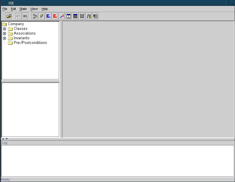
Let's get back to the example. The window that appears after starting USE can be seen in the following screen shot (click on the picture to get an enlarged version).
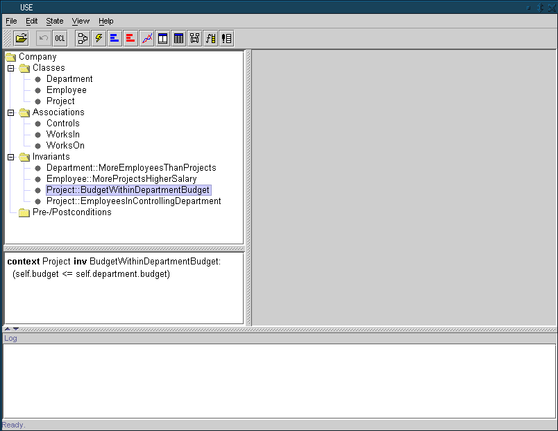
On the left is a tree view showing the contents (classes, associations, invariants, and pre- and postconditions) of the model. The next picture shows the expanded tree with all model elements. One of the invariants is selected and its definition is shown in the panel below the tree.
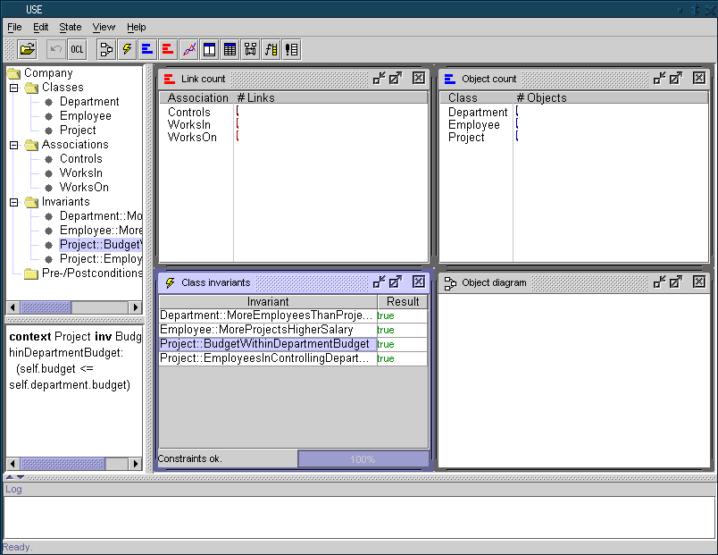
The large area on the right is a workspace where you can open views visualizing different aspects of a system. Views can be created any time by choosing an entry from the view menu or directly by a toolbar button. There is no limit on active views. The next screen shot displays the main window after the creation of four views.
The two upper views list the names of classes and associations defined in the model and shows the number of objects and links in the current system state. The initial system state is empty, i.e., there are no objects and links yet. The view at the lower left displays a list of OCL invariants and their results. As you can see, all invariants are true in the empty system state. Finally, the lower right view will show an object diagram once we have created objects and links.
State|Create object opens a
dialog where this information can be entered.
Alternatively, the following command can be used at the prompt to achieve the same effect.
And, even simpler, an object can be created via drag & drop. Just select a class in the model browser and drag it to the object diagram.
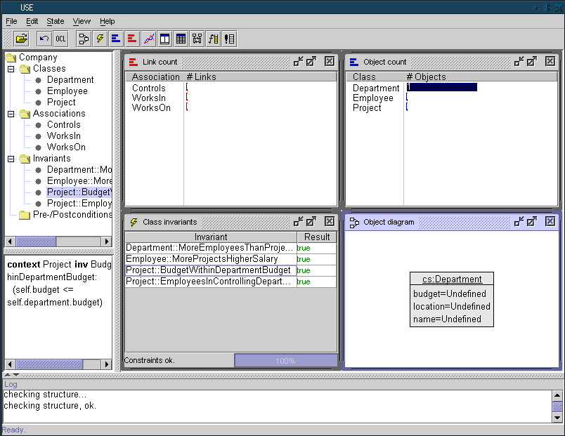
Note the change in the system state views. The upper right view indicates that there is now one department object, and the object diagram shows this object graphically.
A context menu available on a right mouse click in the object diagram provides several display options. For example, the automatic layout can be turned off, the layout of the diagram can be saved and restored from a file, etc. In the previous picture we have turned on the display of attribute values. You can see that the attribute values of the department object are all undefined. For changing attribute values, we can use the set command:
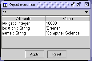
Attributes can also be changed with an object properties
view. If you choose View|Create|Object Properties
from the View menu and select the cs object, you get the
following view where you can inspect and change attributes of the
selected object:
We continue by adding two employee objects and setting their attributes (Again, we use the command line interface here, but the same can be achieved by using the previously discussed steps in the graphical user interface).
Now we have three objects, a department and two employees, but
still no connections between them. The layout in the object diagram is
continuously refined and updated. This can be turned off by
deselecting the option Auto-Layout in the context menu of
the object diagram.
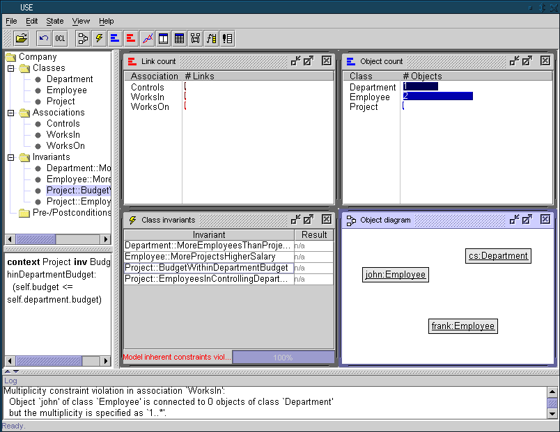
The previous commands resulted in an invalid system state. This is discussed in detail in the next section.
The invariant view indicates some problem with the new system state. The message says: Model inherent constraints violated. Model inherent constraints are constraints defined implicitly by a UML model (in contrast to explicit OCL constraints). The details about this message are shown in the Log panel at the bottom of the screen (they are also available by issuing a check command at the prompt):
The problem here is that we have specified in the model that each employee has to be related to at least one department object (see the class diagram above). In our current state, no employee has a link to a department. In order to fix this, we insert the missing links into the WorksIn association:
Links can also be inserted by selecting the objects to be connected
in the object diagram and choosing the insert command
from the context menu.
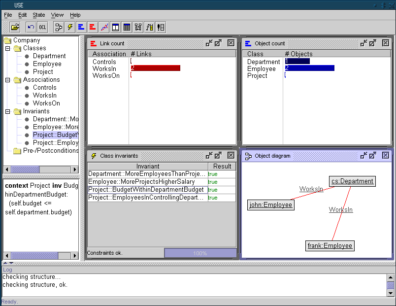
The new state shows the links in the object diagram as red edges between the employee objects and the department object. The invariants are satisfied again.
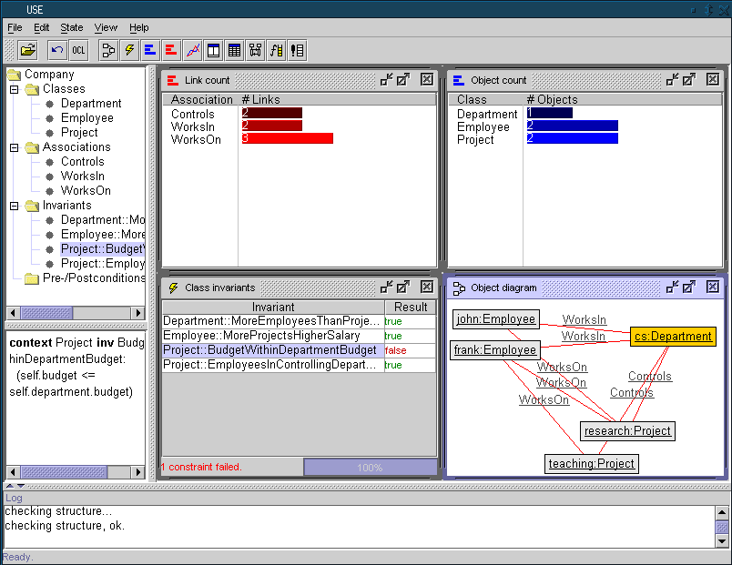
We have seen that class invariants are checked automatically each time a system state changes. This section shows how invariants can be analyzed. We continue the example by adding two projects and linking them to the existing employees and the department:
The resulting state is shown below.
In this state, three of the four invariants are true but one fails. The failing one has the name BudgetWithinDepartmentBudget. This invariant states that The budget of a project must not exceed the budget of the controlling department. Obviously, one of the two projects in our example must have a budget higher than the budget of the department.
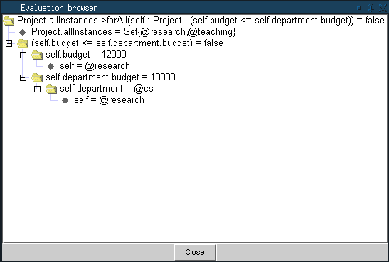
The value false finally resulting from an evaluation of an invariant is not very helpful in finding the reason for an illegal system state. An evaluation browser provides a more detailed view of an expression by showing the results of all sub-expressions. Double-clicking on an invariant will open an evaluation browser:
The root node in the evaluation browser shows the complete expression and its result (which is false for the chosen invariant). For each component of an expression there are child nodes displaying the sub-expressions and their results. You can see that the argument expression of the forAll quantifier is false, thus making the whole expression result false. In this sub-expression, the variable self is bound to the object research. The evaluation browser has helped to find out that it is the budget attribute value of this object which causes the invariant to fail.
The OCL parser and interpreter of USE allows the evaluation of
arbitrary OCL expressions. The menu item State|Evaluate OCL
expression opens a dialog where expressions can be entered and
evaluated.
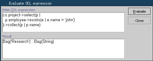
The following example shows a complex expression navigating from a department over projects to employees. The expression finds all projects of the computer science department in which an employee called john is involved.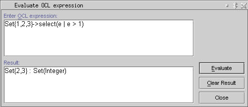
Home|People|Teaching|PublicationsLast change: 17.04.2008 by Fabian Buettner (green@informatik.uni-bremen.de)